Cross Sectional Drawings
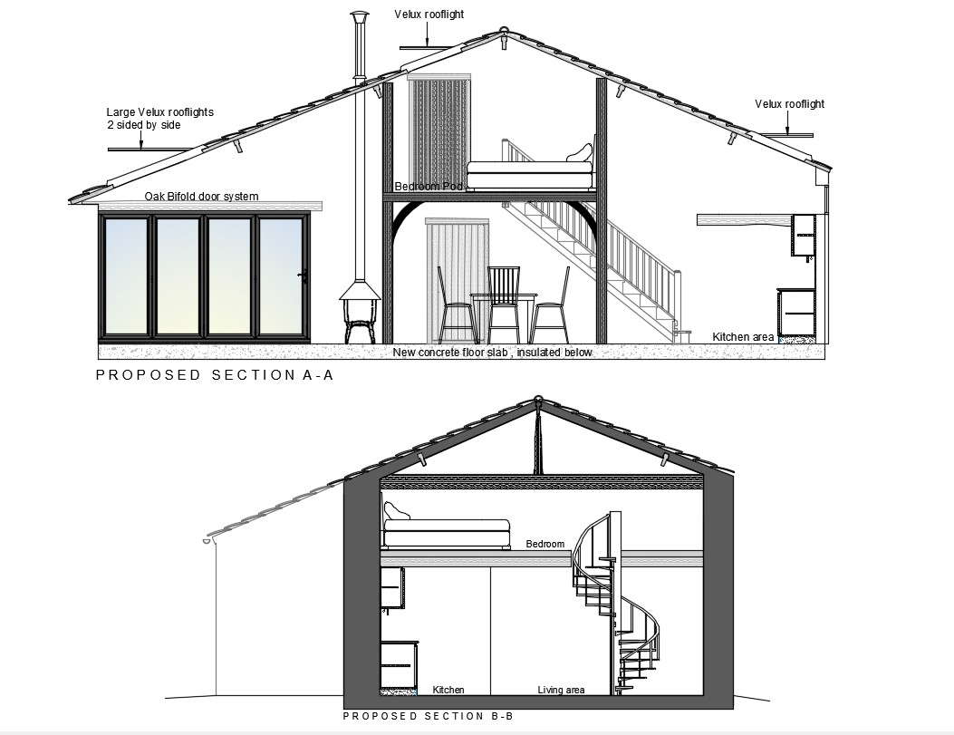
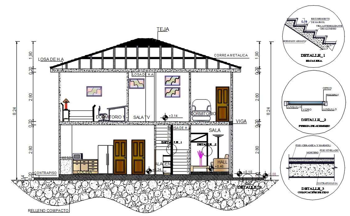
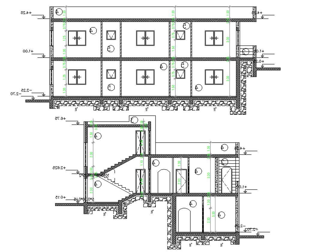
Cross Sectional Drawings - Web learn the basic steps in preparing cross section and longitudinal sections for your architectural drawings.follow me on my official facebook account for your. Actually, it is an imaginary cutting plane taken through the object, since the object is imagined as being cut through at a desired location. It is used to improve the visualization and clarity of new designs, clarify multiview drawings, reveal interior features of parts, and facilitate the dimensioning of drawings. It is traditionally crosshatched with the style of crosshatching often indicating the types of materials being used. Web a revolved view is a cross section of an existing view that is revolved 90 degrees around a cutting plane projection. Cutting plane a surface cut by the saw in the drawing above is a cutting plane. Choose a cross section line. A cross section is a view created by cutting through the short side of the building. Web isometric drawings can show overall arrangement clearly, but not the details and the dimensions. Sections normally comprise of two parts, firstly the section cut indicator with identification. Web detail from walled city cross section. On the floor plan drawing above, at the upper and lower left there are two as surrounded by circular icons with an arrow. This is as if you cut through a space vertically and stood directly in front looking straight at it. Web isometric drawings can show overall arrangement clearly, but not the details and the dimensions. Used to indicate where the cutting plane cuts the material. This type of drawing shows the cross section, then a perspective of the spaces beyond. Web learn the basic steps in preparing cross section and longitudinal sections for your architectural drawings.follow me on my official facebook account for your. Type the desired information in the text field and click ok. The section truly is the mother of visual storytellers, and the perfect inspiration for the one drawing challenge — a global ideas competition in which a single drawing could win you $2,500 (sign up today!). Cutting plane a surface cut by the saw in the drawing above is a cutting plane. Less common, but still used section views include revolved and removed sections. Use labels, arrows, and other visual cues to indicate the different. Web section drawing definition. The cross section of a rectangular pyramid is a rectangle. It is used to improve the visualization and clarity of new designs, clarify multiview drawings, reveal interior features of parts, and facilitate the. Web isometric drawings can show overall arrangement clearly, but not the details and the dimensions. For mechanical drawings section views are used to reveal interior features. Used to show where the object is being cut. Use labels, arrows, and other visual cues to indicate the different. Also mark on any roads or rivers etc. Section lines are thin and the symbols (type of lines) are chosen according to the material of the object. In the figure a regular multiview drawing and a. Web just as an apple can be sectioned any way you choose, so can an object in a sectional view of a drawing or sketch. Web a section view can easily display. Begin by drawing the outline of the object or system, and then add the different layers or sections that make up its internal structure. Web learn the basic steps in preparing cross section and longitudinal sections for your architectural drawings.follow me on my official facebook account for your. Web the technique called section views is a very important aspect of. Type the desired information in the text field and click ok. Actually, it is an imaginary cutting plane taken through the object, since the object is imagined as being cut through at a desired location. Round the corners of the pool shell with the smooth tool. Choose a cross section line. It is used to improve the visualization and clarity. It is used to improve the visualization and clarity of new designs, clarify multiview drawings, reveal interior features of parts, and facilitate the dimensioning of drawings. This will save space on the drawing with over population of reference. Web the cross section of this circular cylinder is a circle. A cross section is a view created by cutting through the. Actually, it is an imaginary cutting plane taken through the object, since the object is imagined as being cut through at a desired location. Used to indicate where the cutting plane cuts the material. Cross sections are usually parallel to the base like above, but can be in any direction. The cross hatching feature is an indicator for cross sectional. For square buildings, objects, and assemblies, a cross section can mean any section cut. Actually, it is an imaginary cutting plane taken through the object, since the object is imagined as being cut through at a desired location. Cross sections are usually parallel to the base like above, but can be in any direction. Web a revolved view is a. We don't draw the rest of the object, just the shape made when you cut through. Here are seven more examples that illustrate just how brilliantly this type of drawing can. Actually, it is an imaginary cutting plane taken through the object, since the object is imagined as being cut through at a desired location. Web select the general markup. A section is drawn from a vertical plane slicing through a building. Begin by drawing the outline of the object or system, and then add the different layers or sections that make up its internal structure. To create a cross section, first draw a line on your floor plan that cuts through a section of the house for which you. For square buildings, objects, and assemblies, a cross section can mean any section cut. This will save space on the drawing with over population of reference. It is used to improve the visualization and clarity of new designs, clarify multiview drawings, reveal interior features of parts, and facilitate the dimensioning of drawings. Web sectional drawings are multiview technical drawings that contain special views of a part or parts, a view that reveal interior features. This type of drawing shows the cross section, then a perspective of the spaces beyond. This is as if you cut through a space vertically and stood directly in front looking straight at it. Web learn the basic steps in preparing cross section and longitudinal sections for your architectural drawings.follow me on my official facebook account for your. Choose a cross section line. The section plane lies perpendicular to a longitudinal section, and it’s used to show the inside of a building the same way. Web a section or cross section is a view generated from a part or assembly on a cutting plane or multiple cutting planes that reveals the outlines on the inside or assembly fits. On the floor plan drawing above, at the upper and lower left there are two as surrounded by circular icons with an arrow. Begin by drawing the outline of the object or system, and then add the different layers or sections that make up its internal structure. Cross section is the preferred option compared to hidden lines as it brings more clarity. Mark a at the start of the transect and b at the end. For mechanical drawings section views are used to reveal interior features. Also mark on any roads or rivers etc.
Cross Sections Drawings Residential Design Inc
Cross section drawings
House Cross Section Drawing Cadbull
House Cross Section AutoCAD Drawing Download DWG File Cadbull
AutoCAD House Building Cross Section Drawing DWG File Cadbull

Architectural Cross Section Drawing Southbank Centre Work
14 House Cross Section Drawing That Will Bring The Joy Home Plans
Section Drawing Architecture at Explore collection
House Building Cross Section Drawing DWG File Cadbull

How to Draw House Cross Sections
Web Lines Used In Section Views.
You Can Use A Cross Section Created In The 3D Model As The Cutting Plane, Or You Can Create One On The Fly While Placing The View.
Web A Section View Can Easily Display Some Of The Part Features That Are Not Evident When Looking Just From The Outset.
A Text Object With A Line With Arrow Attached Is Created At The Location Where You Clicked.
Related Post: